最近要使用ESP32进行ADC采样,需要对ESP32的ADC采样率进行设置,查阅后发现网上这方面的资料非常少,所以把配置过程写下来以供大家参考
文章目录
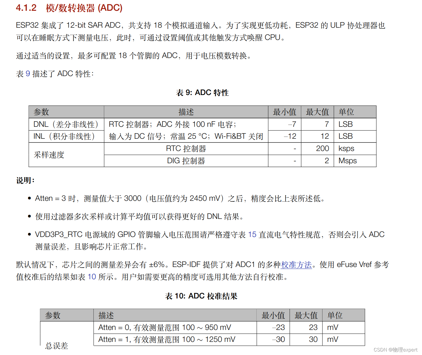
打开ESP32的技术规格书第34页,可见ESP32具有2个12位的逐次逼近型ADC,他有RTC和DIG两个控制器,其中RTC控制器最大采样率为200KSPS,DIG控制器为2MSPS,如果我们需要采样频率较高的信号,就必须使用DIG控制器。
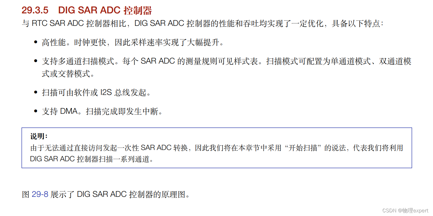
打开ESP32的技术参考手册第577页找到DIG控制器,可见我们为了追求最大的采样率,应该考虑使用DMA配合ADC使用。
打开ESP-IDF的官方ADC_DMA示例程序,这里我用的是VSCODE+ESP-IDF(v4.4)插件,由于我使用的是ESP32芯片,所以我将所有用于适配其他芯片部分的代码删除,删除后的示例代码如下:
#include <string.h>
#include <stdio.h>
#include "sdkconfig.h"
#include "esp_log.h"
#include "freertos/FreeRTOS.h"
#include "freertos/task.h"
#include "freertos/semphr.h"
#include "driver/adc.h"

#define TIMES 1000 //一次的采样点数*2
#define GET_UNIT(x) ((x >> 3) & 0x1)

#if CONFIG_IDF_TARGET_ESP32
#define ADC_RESULT_BYTE 2
#define ADC_CONV_LIMIT_EN 1                  // For ESP32, this should always be set to 1
#define ADC_CONV_MODE ADC_CONV_SINGLE_UNIT_1 // ESP32 only supports ADC1 DMA mode
#define ADC_OUTPUT_TYPE ADC_DIGI_OUTPUT_FORMAT_TYPE1
#endif

#if CONFIG_IDF_TARGET_ESP32
static uint16_t adc1_chan_mask = BIT(7);
static uint16_t adc2_chan_mask = 0;
static adc_channel_t channel[1] = {ADC1_CHANNEL_7}; //设置ADC引脚
#endif

static uint32_t ret_num = 0;
static uint8_t result[TIMES] = {0}; //采样结果存放数组

static const char *TAG = "{adc}";
int countNum;

static void continuous_adc_init(uint16_t adc1_chan_mask, uint16_t
adc2_chan_mask, adc_channel_t *channel, uint8_t channel_num)
{
    adc_digi_init_config_t adc_dma_config = {
        .max_store_buf_size = 1024,
        .conv_num_each_intr = TIMES,
        .adc1_chan_mask = adc1_chan_mask,
        .adc2_chan_mask = adc2_chan_mask,
    };
    ESP_ERROR_CHECK(adc_digi_initialize(&adc_dma_config));

    adc_digi_configuration_t dig_cfg = {
        .conv_limit_en = ADC_CONV_LIMIT_EN,
        .conv_limit_num = 250,
        .sample_freq_hz = 100000, //采样率
        .conv_mode = ADC_CONV_MODE,
        .format = ADC_OUTPUT_TYPE,
    };

    adc_digi_pattern_config_t adc_pattern[SOC_ADC_PATT_LEN_MAX] = {0};
    dig_cfg.pattern_num = channel_num;
    for (int i = 0; i < channel_num; i++)
    {
        uint8_t unit = GET_UNIT(channel[i]);
        uint8_t ch = channel[i] & 0x7;
        adc_pattern[i].atten = ADC_ATTEN_DB_11; //衰减倍率
        adc_pattern[i].channel = ch;
        adc_pattern[i].unit = unit;
        adc_pattern[i].bit_width = SOC_ADC_DIGI_MAX_BITWIDTH; //采样位数

        // ESP_LOGI(TAG, "adc_pattern[%d].atten is :%x", i, adc_pattern[i].atten);
        //  ESP_LOGI(TAG, "adc_pattern[%d].channel is :%x", i, adc_pattern[i].channel);
        // ESP_LOGI(TAG, "adc_pattern[%d].unit is :%x", i, adc_pattern[i].unit);
    }
    dig_cfg.adc_pattern = adc_pattern;
    ESP_ERROR_CHECK(adc_digi_controller_configure(&dig_cfg));
}

#if !CONFIG_IDF_TARGET_ESP32
static bool check_valid_data(const adc_digi_output_data_t *data)
{
    const unsigned int unit = data->type2.unit;
    if (unit > 2)
        return false;
    if (data->type2.channel >= SOC_ADC_CHANNEL_NUM(unit))
        return false;

    return true;
}
#endif

void app_main(void)
{


    memset(result, 0xcc, TIMES);

    continuous_adc_init(adc1_chan_mask, adc2_chan_mask, channel, sizeof(channel) / sizeof(adc_channel_t));
    adc_digi_start();


  while(1)
  {
        adc_digi_read_bytes(result, TIMES, &ret_num, ADC_MAX_DELAY);
        for (int i = 0; i < ret_num; i += ADC_RESULT_BYTE)
        {
            adc_digi_output_data_t *p = (void *)&result[i];
            // ESP_LOGI(TAG, "%d", p->type1.data);
            // printf("{value}%d\n", p->type1.data);
            // vTaskDelay(10/ portTICK_PERIOD_MS);
        }
  }

}
首先ADC的采样率等于单位时间采样的点数,所以需要定义一个变量为countNum,这个变量用于累计单位时间的采样点的个数,把countNum放到ADC采样部分,每完成一次ADC采样就加一,使用freertos中的任务创建函数xTaskCreate(countTask, “countTask”, 1024 * 10, NULL, 2, NULL);,在这个函数中,使用死循环,每间隔一秒打印一次countNum的值,因为这个任务与ADC采样并行运行,所以countNum即为ADC的采样率,代码如下
void countTask(void *param)//创建获取采样率任务
{

    while (1)
    {

        vTaskDelay(1000 / portTICK_PERIOD_MS);
        printf("{count}%d\n", countNum);
        countNum = 0;
    }
}
 adc_digi_read_bytes(result, TIMES, &ret_num, ADC_MAX_DELAY);//ADC采样数据读取
        for (int i = 0; i < ret_num; i += ADC_RESULT_BYTE)
        {
            adc_digi_output_data_t *p = (void *)&result[i];
            value[i] = p->type1.data;

            // ESP_LOGI(TAG, "%d", p->type1.data);
            // printf("{value}%d\n", p->type1.data);
            countNum++;//采样率计数
            // vTaskDelay(10/ portTICK_PERIOD_MS);
        }
对ESP32ADC的配置实际上就是对ADC的DIG控制器的配置,在adc.h中可以找到adc_digi_init_config_t和adc_digi_configuration_t结构体的定义,修改这些结构体中的成员就可以改变ADC的相关参数。
typedef struct adc_digi_init_config_s {
    uint32_t max_store_buf_size;    ///< Max length of the converted data that driver can store before they are processed.
    uint32_t conv_num_each_intr;    ///< Bytes of data that can be converted in 1 interrupt.
    uint32_t adc1_chan_mask;        ///< Channel list of ADC1 to be initialized.
    uint32_t adc2_chan_mask;        ///< Channel list of ADC2 to be initialized.
} adc_digi_init_config_t;
typedef struct {
    bool conv_limit_en;                      ///< To limit ADC conversion times. Conversion stops after finishing `conv_limit_num` times conversion
    uint32_t conv_limit_num;                 ///< Set the upper limit of the number of ADC conversion triggers. Range: 1 ~ 255.
    uint32_t pattern_num;                    ///< Number of ADC channels that will be used
    adc_digi_pattern_config_t *adc_pattern;    ///< List of configs for each ADC channel that will be used
    uint32_t sample_freq_hz;  /*!< The expected ADC sampling frequency in Hz. Range: 611Hz ~ 83333Hz
                                   Fs = Fd / interval / 2
                                   Fs: sampling frequency;
                                   Fd: digital controller frequency, no larger than 5M for better performance
                                   interval: interval between 2 measurement trigger signal, the smallest interval should not be smaller than the ADC measurement period, the largest interval should not be larger than 4095 */
    adc_digi_convert_mode_t conv_mode;      ///< ADC DMA conversion mode, see `adc_digi_convert_mode_t`.
    adc_digi_output_format_t format;        ///< ADC DMA conversion output format, see `adc_digi_output_format_t`.
} adc_digi_configuration_t;
我在初始化代码中做出了如下修改
(1)增大max_store_buf_size使得ADC一次可以采集更多的点数
(2)增加TIMES的值,方便观察现象
(3)修改sample_freq_hz,即修改采样率,最大可到达2000000hz
adc_digi_init_config_t adc_dma_config = {
        .max_store_buf_size = 4096,//最大采样缓存
        .conv_num_each_intr = TIMES,
        .adc1_chan_mask = adc1_chan_mask,
        .adc2_chan_mask = adc2_chan_mask,
    };
adc_digi_configuration_t dig_cfg = {
        .conv_limit_en = ADC_CONV_LIMIT_EN,
        .conv_limit_num = 250,
        .sample_freq_hz = 100000, //采样率
        .conv_mode = ADC_CONV_MODE,
        .format = ADC_OUTPUT_TYPE,
    };
最后附上完整代码
#include <string.h>
#include <stdio.h>
#include "sdkconfig.h"
#include "esp_log.h"
#include "freertos/FreeRTOS.h"
#include "freertos/task.h"
#include "freertos/semphr.h"
#include "driver/adc.h"

#define TIMES 2000 //一次的采样点数*2
#define GET_UNIT(x) ((x >> 3) & 0x1)

#if CONFIG_IDF_TARGET_ESP32
#define ADC_RESULT_BYTE 2
#define ADC_CONV_LIMIT_EN 1                  // For ESP32, this should always be set to 1
#define ADC_CONV_MODE ADC_CONV_SINGLE_UNIT_1 // ESP32 only supports ADC1 DMA mode
#define ADC_OUTPUT_TYPE ADC_DIGI_OUTPUT_FORMAT_TYPE1
#endif

#if CONFIG_IDF_TARGET_ESP32
static uint16_t adc1_chan_mask = BIT(7);
static uint16_t adc2_chan_mask = 0;
static adc_channel_t channel[1] = {ADC1_CHANNEL_7}; //设置ADC引脚
#endif

static uint32_t ret_num = 0;
static uint8_t result[TIMES] = {0}; //采样结果存放数组
static uint16_t value[2000] = {0};

static const char *TAG = "{adc}";
int countNum;

void countTask(void *param)
{

    while (1)
    {

        vTaskDelay(1000 / portTICK_PERIOD_MS);
        printf("{count}%d\n", countNum);
        // printf("{value}%d\n",p->type1.data);
        countNum = 0;
    }
}

static void continuous_adc_init(uint16_t adc1_chan_mask, uint16_t adc2_chan_mask, adc_channel_t *channel, uint8_t channel_num)
{
    adc_digi_init_config_t adc_dma_config = {
        .max_store_buf_size = 4096,//最大采样缓存
        .conv_num_each_intr = TIMES,
        .adc1_chan_mask = adc1_chan_mask,
        .adc2_chan_mask = adc2_chan_mask,
    };
    ESP_ERROR_CHECK(adc_digi_initialize(&adc_dma_config));

    adc_digi_configuration_t dig_cfg = {
        .conv_limit_en = ADC_CONV_LIMIT_EN,
        .conv_limit_num = 250,
        .sample_freq_hz = 100000, //采样率
        .conv_mode = ADC_CONV_MODE,
        .format = ADC_OUTPUT_TYPE,
    };

    adc_digi_pattern_config_t adc_pattern[SOC_ADC_PATT_LEN_MAX] = {0};
    dig_cfg.pattern_num = channel_num;
    for (int i = 0; i < channel_num; i++)
    {
        uint8_t unit = GET_UNIT(channel[i]);
        uint8_t ch = channel[i] & 0x7;
        adc_pattern[i].atten = ADC_ATTEN_DB_11; //衰减倍率
        adc_pattern[i].channel = ch;
        adc_pattern[i].unit = unit;
        adc_pattern[i].bit_width = SOC_ADC_DIGI_MAX_BITWIDTH; //采样位数

        // ESP_LOGI(TAG, "adc_pattern[%d].atten is :%x", i, adc_pattern[i].atten);
        //  ESP_LOGI(TAG, "adc_pattern[%d].channel is :%x", i, adc_pattern[i].channel);
        // ESP_LOGI(TAG, "adc_pattern[%d].unit is :%x", i, adc_pattern[i].unit);
    }
    dig_cfg.adc_pattern = adc_pattern;
    ESP_ERROR_CHECK(adc_digi_controller_configure(&dig_cfg));
}

#if !CONFIG_IDF_TARGET_ESP32
static bool check_valid_data(const adc_digi_output_data_t *data)
{
    const unsigned int unit = data->type2.unit;
    if (unit > 2)
        return false;
    if (data->type2.channel >= SOC_ADC_CHANNEL_NUM(unit))
        return false;

    return true;
}
#endif

void app_main(void)
{
    xTaskCreate(countTask, "countTask", 1024 * 10, NULL, 2, NULL); //创建任务

    memset(result, 0xcc, TIMES);

    continuous_adc_init(adc1_chan_mask, adc2_chan_mask, channel, sizeof(channel) / sizeof(adc_channel_t));
    adc_digi_start();


        adc_digi_read_bytes(result, TIMES, &ret_num, ADC_MAX_DELAY);
        for (int i = 0; i < ret_num; i += ADC_RESULT_BYTE)
        {
            adc_digi_output_data_t *p = (void *)&result[i];
            value[i] = p->type1.data;

            // ESP_LOGI(TAG, "%d", p->type1.data);
            // printf("{value}%d\n", p->type1.data);
            countNum++;
            // vTaskDelay(10/ portTICK_PERIOD_MS);
        }
        for (int i = 0; i < ret_num; i += ADC_RESULT_BYTE)
        {
            printf("{value}%d\n", value[i]);
        }

}
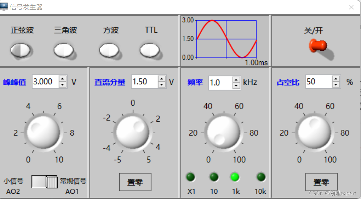
首先将采样率配置为1000000hz,即sample_freq_hz = 100000,将esp32与信号发生器连接,信号发生器设置频率为1kHz,一次采样点数为1000,按下复位键开始一次采样1000个点,存入数组中,接着将数组中的值输出至串口绘图软件观察
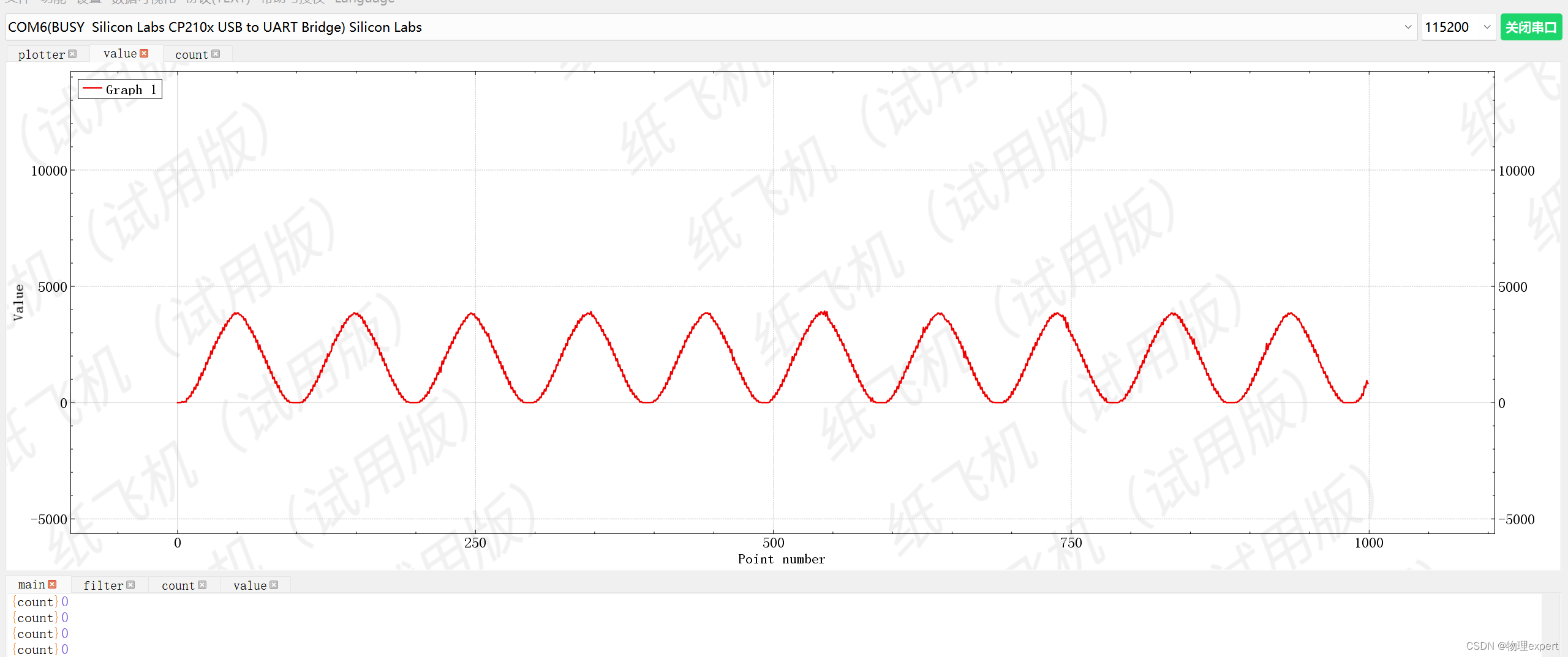
可见esp32采样到了10个波形,这说明adc的采样率已经配置为了100000hz
(1)不能将串口输出与ADC采集放在同一个循环中,否则ADC采样率会被串口发送程序拉低,必须独立开。
(2)对于ESP32来说,最好先关闭看门狗,防止ADC读取数据时重启。
(3)数组建立时前面必须加上static,否则单片机内存会爆炸。
(4)rtc控制器与dig控制器最大的区别在于采样率,dig可以配合DMA达到非常高的采样率,但是无法将采样率配置的很低,rtc控制器则相反,可以根据需要使用不同的控制器。
(5)如果将sample_freq_hz = 200000,会发现countNum并不是200000,这是正常现象,因为freertos的多任务系统会降低采样率,但得益于ESP32的240MHz主频,影响一般不大。
(6)ADC2无法和WiFi同时使用。
我有一个在Linux服务器上运行的ruby脚本。它不使用rails或任何东西。它基本上是一个命令行ruby脚本,可以像这样传递参数:./ruby_script.rbarg1arg2如何将参数抽象到配置文件(例如yaml文件或其他文件)中?您能否举例说明如何做到这一点?提前谢谢你。 最佳答案 首先,您可以运行一个写入YAML配置文件的独立脚本:require"yaml"File.write("path_to_yaml_file",[arg1,arg2].to_yaml)然后,在您的应用中阅读它:require"yaml"arg
我已经在Sinatra上创建了应用程序,它代表了一个简单的API。我想在生产和开发上进行部署。我想在部署时选择,是开发还是生产,一些方法的逻辑应该改变,这取决于部署类型。是否有任何想法,如何完成以及解决此问题的一些示例。例子:我有代码get'/api/test'doreturn"Itisdev"end但是在部署到生产环境之后我想在运行/api/test之后看到ItisPROD如何实现? 最佳答案 根据SinatraDocumentation:EnvironmentscanbesetthroughtheRACK_ENVenvironm
之前在培训新生的时候,windows环境下配置opencv环境一直教的都是网上主流的vsstudio配置属性表,但是这个似乎对新生来说难度略高(虽然个人觉得完全是他们自己的问题),加之暑假之后对cmake实在是爱不释手,且这样配置确实十分简单(其实都不需要配置),故斗胆妄言vscode下配置CV之法。其实极为简单,图比较多所以很长。如果你看此文还配不好,你应该思考一下是不是自己的问题。闲话少说,直接开始。0.CMkae简介有的人到大二了都不知道cmake是什么,我不说是谁。CMake是一个开源免费并且跨平台的构建工具,可以用简单的语句来描述所有平台的编译过程。它能够根据当前所在平台输出对应的m
文章目录1.开发板选择*用到的资源2.串口通信(个人理解)3.代码分析(注释比较详细)1.主函数2.串口1配置3.串口2配置以及中断函数4.注意问题5.源码链接1.开发板选择我用的是STM32F103RCT6的板子,不过代码大概在F103系列的板子上都可以运行,我试过在野火103的霸道板上也可以,主要看一下串口对应的引脚一不一样就行了,不一样的就更改一下。*用到的资源keil5软件这里用到了两个串口资源,采集数据一个,串口通信一个,板子对应引脚如下:串口1,TX:PA9,RX:PA10串口2,TX:PA2,RX:PA32.串口通信(个人理解)我就从串口采集传感器数据这个过程说一下我自己的理解,
注意:本文主要掌握DCN自研无线产品的基本配置方法和注意事项,能够进行一般的项目实施、调试与运维AP基本配置命令AP登录用户名和密码均为:adminAP默认IP地址为:192.168.1.10AP默认情况下DHCP开启AP静态地址配置:setmanagementstatic-ip192.168.10.1AP开启/关闭DHCP功能:setmanagementdhcp-statusup/downAP设置默认网关:setstatic-ip-routegeteway192.168.10.254查看AP基本信息:getsystemgetmanagementgetmanaged-apgetrouteAP配
1.1.1 YARN的介绍 为克服Hadoop1.0中HDFS和MapReduce存在的各种问题⽽提出的,针对Hadoop1.0中的MapReduce在扩展性和多框架⽀持⽅⾯的不⾜,提出了全新的资源管理框架YARN. ApacheYARN(YetanotherResourceNegotiator的缩写)是Hadoop集群的资源管理系统,负责为计算程序提供服务器计算资源,相当于⼀个分布式的操作系统平台,⽽MapReduce等计算程序则相当于运⾏于操作系统之上的应⽤程序。 YARN被引⼊Hadoop2,最初是为了改善MapReduce的实现,但是因为具有⾜够的通⽤性,同样可以⽀持其他的分布式计算模
我是ruby的新手,正在配置IRB。我喜欢pretty-print(需要'pp'),但总是输入pp来漂亮地打印它似乎很麻烦。我想做的是默认情况下让它漂亮地打印出来,所以如果我有一个var,比如说,'myvar',然后键入myvar,它会自动调用pretty_inspect而不是常规检查。我从哪里开始?理想情况下,我将能够向我的.irbrc文件添加一个自动调用的方法。有什么想法吗?谢谢! 最佳答案 irb中默认pretty-print对象正是hirb被迫去做。Theseposts解释hirb如何将几乎所有内容转换为ascii表。虽
我想在IRB中浏览文件系统并让提示更改以反射(reflect)当前工作目录,但我不知道如何在每个命令后进行提示更新。最终,我想在日常工作中更多地使用IRB,让bash溜走。我在我的.irbrc中试过这个:require'fileutils'includeFileUtilsIRB.conf[:PROMPT][:CUSTOM]={:PROMPT_N=>"\e[1m:\e[m",:PROMPT_I=>"\e[1m#{pwd}>\e[m",:PROMPT_S=>"FOO",:PROMPT_C=>"\e[1m#{pwd}>\e[m",:RETURN=>""}IRB.conf[:PROMPT_MO
我正在使用Ruby/Mechanize编写一个“自动填写表格”应用程序。它几乎可以工作。我可以使用精彩CharlesWeb代理以查看服务器和我的Firefox浏览器之间的交换。现在我想使用Charles查看服务器和我的应用程序之间的交换。Charles在端口8888上代理。假设服务器位于https://my.host.com。.一件不起作用的事情是:@agent||=Mechanize.newdo|agent|agent.set_proxy("my.host.com",8888)end这会导致Net::HTTP::Persistent::Error:...lib/net/http/pe
如果特定语言环境中缺少翻译,如何配置i18n以使用en语言环境翻译?当前已插入翻译缺失消息。我正在使用RoR3.1。 最佳答案 找到相似的question这里是答案:#application.rb#railswillfallbacktoconfig.i18n.default_localetranslationconfig.i18n.fallbacks=true#railswillfallbacktoen,nomatterwhatissetasconfig.i18n.default_localeconfig.i18n.fallback