电子模块|心率血氧传感器模块MAX30102及其驱动代码
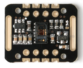
MAX30102是一个集成的脉搏血氧仪和心率监测仪生物传感器的模块。
它集成了一个红光LED和一个红外光LED、光电检测器、光器件,以及带环境光抑制的低噪声电子电路。
MAX30102采用一个1.8V电源和一个独立的5.0V用于内部LED的电源,应用于可穿戴设备进行心率和血氧采集检测,佩戴于手指点耳垂和手腕处。
标准的I2C兼容的通信接口可以将采集到的数值传输给Arduino、KL25Z、STM32、STC51等单片机进行心率和血氧计算。
此外,该芯片还可以通过软件关断模块,待机电流接近为零,实现电源始终维持供电状态。
主要参数:
| 产品名称 | MAX30102 心率模块 |
|---|---|
| LED峰值波长器 | 660nm/880nm |
| LED供电电压 | 3.3 ~ 5V |
| 检测信号类型 | 光反射信号(PPG) |
| 输出信号接口 | I2C接口 |
| 通信接口电压 | 1.8 ~ 3.3V ~ 5V(可选) |
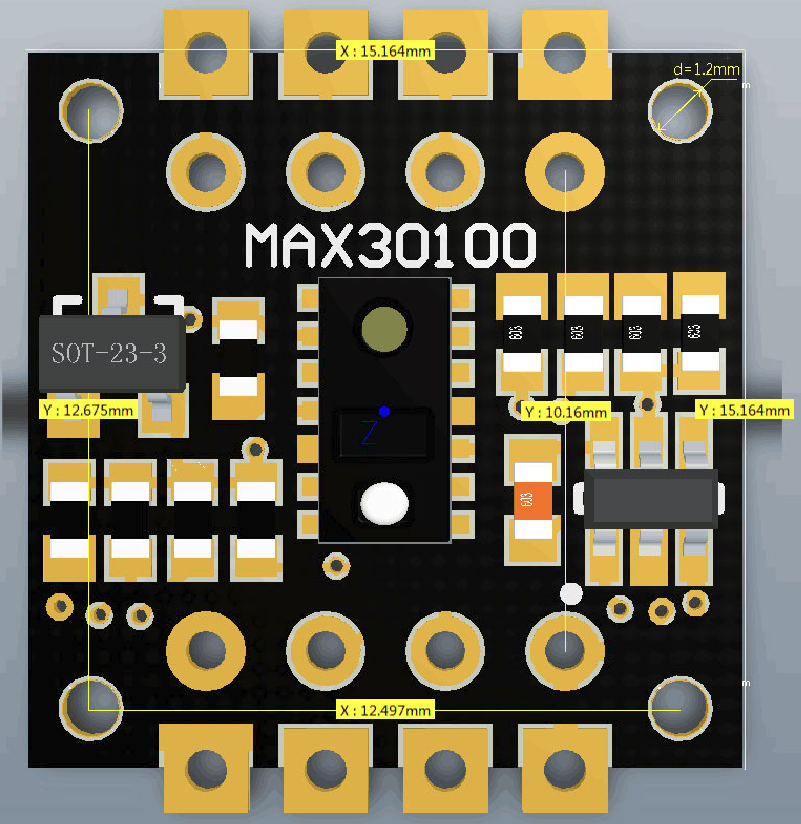
产品尺寸:
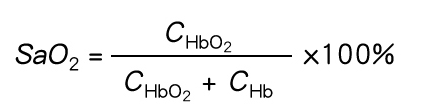
光溶积法:利用人体组织在血管搏动时造成透光率不同来进行脉搏和血氧饱和度测量
光源:采用对动脉血中痒合血红蛋白(HbO2)和血红蛋白(Hb)有选择性的特定波长的发光二极管
透光率转化为电信号:动脉搏动充血容积变化导致这束光的透光率发送改变,此时由光电变换接收经人体组织反射光线,转变为电信号并将其放大输出。
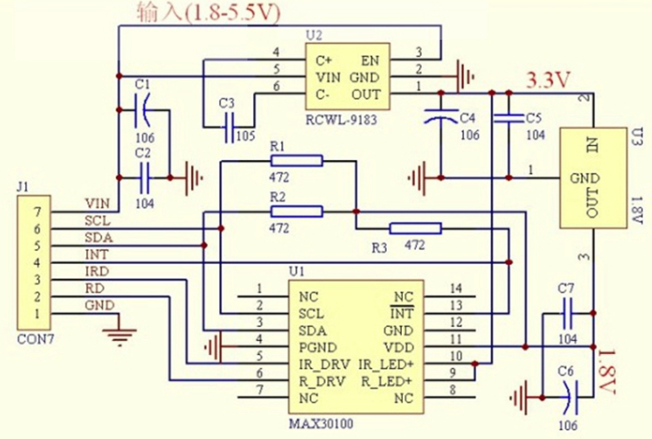
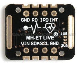
引脚说明
| 名称 | 管教定义 |
|---|---|
| VIN | 电源输入 1.6V-5.5V |
| 3位焊盘 | 选择总线的上拉电平,取决于引脚主控电压可选1.8v或者3.3v |
| SDA | IIC-SDA |
| SCL | IIC-SCL |
| GND | 地 |
| INT | INT 低电平有效中断(漏极开路)MAX30102 的中断引脚 |
| IRD | IR_DRV IR LED阴极和LED驱动器连接点 一般不接 |
| RD | R_DRV 红色LED阴极和LED驱动器连接点 一般不接 |
使用STM32F103C8T6最小系统开发板验证。
接线如下:
MAX30102模块接口:PB9-SDA,PB8-SCL,PB7-INT
PA2/PA3为串口传输口TX和RX,波特率设置为115200
PC13为显示LED
#include "mbed.h"
#include "MAX30102.h"


I2C i2c(I2C_SDA, I2C_SCL);//SDA-PB9,SCL-PB8


bool maxim_max30102_write_reg(uint8_t uch_addr, uint8_t uch_data)
/**
* \brief        Write a value to a MAX30102 register
* \par          Details
*               This function writes a value to a MAX30102 register
*
* \param[in]    uch_addr    - register address
* \param[in]    uch_data    - register data
*
* \retval       true on success
*/
{
  char ach_i2c_data[2];
  ach_i2c_data[0]=uch_addr;
  ach_i2c_data[1]=uch_data;

  if(i2c.write(I2C_WRITE_ADDR, ach_i2c_data, 2, false)==0)
    return true;
  else
    return false;
}

bool maxim_max30102_read_reg(uint8_t uch_addr, uint8_t *puch_data)
/**
* \brief        Read a MAX30102 register
* \par          Details
*               This function reads a MAX30102 register
*
* \param[in]    uch_addr    - register address
* \param[out]   puch_data    - pointer that stores the register data
*
* \retval       true on success
*/
{
  char ch_i2c_data;
  ch_i2c_data=uch_addr;
  if(i2c.write(I2C_WRITE_ADDR, &ch_i2c_data, 1, true)!=0)
    return false;
  if(i2c.read(I2C_READ_ADDR, &ch_i2c_data, 1, false)==0)
  {
    *puch_data=(uint8_t) ch_i2c_data;
    return true;
  }
  else
    return false;
}

bool maxim_max30102_init()
/**
* \brief        Initialize the MAX30102
* \par          Details
*               This function initializes the MAX30102
*
* \param        None
*
* \retval       true on success
*/
{
  if(!maxim_max30102_write_reg(REG_INTR_ENABLE_1,0xc0)) // INTR setting
    return false;
  if(!maxim_max30102_write_reg(REG_INTR_ENABLE_2,0x00))
    return false;
  if(!maxim_max30102_write_reg(REG_FIFO_WR_PTR,0x00))  //FIFO_WR_PTR[4:0]
    return false;
  if(!maxim_max30102_write_reg(REG_OVF_COUNTER,0x00))  //OVF_COUNTER[4:0]
    return false;
  if(!maxim_max30102_write_reg(REG_FIFO_RD_PTR,0x00))  //FIFO_RD_PTR[4:0]
    return false;
  if(!maxim_max30102_write_reg(REG_FIFO_CONFIG,0x0f))  //sample avg = 1, fifo rollover=false, fifo almost full = 17
    return false;
  if(!maxim_max30102_write_reg(REG_MODE_CONFIG,0x03))   //0x02 for Red only, 0x03 for SpO2 mode 0x07 multimode LED
    return false;
  if(!maxim_max30102_write_reg(REG_SPO2_CONFIG,0x27))  // SPO2_ADC range = 4096nA, SPO2 sample rate (100 Hz), LED pulseWidth (400uS)
    return false;

  if(!maxim_max30102_write_reg(REG_LED1_PA,0x24))   //Choose value for ~ 7mA for LED1
    return false;
  if(!maxim_max30102_write_reg(REG_LED2_PA,0x24))   // Choose value for ~ 7mA for LED2
    return false;
  if(!maxim_max30102_write_reg(REG_PILOT_PA,0x7f))   // Choose value for ~ 25mA for Pilot LED
    return false;
  return true;
}

bool maxim_max30102_read_fifo(uint32_t *pun_red_led, uint32_t *pun_ir_led)
/**
* \brief        Read a set of samples from the MAX30102 FIFO register
* \par          Details
*               This function reads a set of samples from the MAX30102 FIFO register
*
* \param[out]   *pun_red_led   - pointer that stores the red LED reading data
* \param[out]   *pun_ir_led    - pointer that stores the IR LED reading data
*
* \retval       true on success
*/
{
  uint32_t un_temp;
  unsigned char uch_temp;
  *pun_red_led=0;
  *pun_ir_led=0;
  char ach_i2c_data[6];

  //read and clear status register
  maxim_max30102_read_reg(REG_INTR_STATUS_1, &uch_temp);
  maxim_max30102_read_reg(REG_INTR_STATUS_2, &uch_temp);

  ach_i2c_data[0]=REG_FIFO_DATA;
  if(i2c.write(I2C_WRITE_ADDR, ach_i2c_data, 1, true)!=0)
    return false;
  if(i2c.read(I2C_READ_ADDR, ach_i2c_data, 6, false)!=0)
  {
    return false;
  }
  un_temp=(unsigned char) ach_i2c_data[0];
  un_temp<<=16;
  *pun_red_led+=un_temp;
  un_temp=(unsigned char) ach_i2c_data[1];
  un_temp<<=8;
  *pun_red_led+=un_temp;
  un_temp=(unsigned char) ach_i2c_data[2];
  *pun_red_led+=un_temp;

  un_temp=(unsigned char) ach_i2c_data[3];
  un_temp<<=16;
  *pun_ir_led+=un_temp;
  un_temp=(unsigned char) ach_i2c_data[4];
  un_temp<<=8;
  *pun_ir_led+=un_temp;
  un_temp=(unsigned char) ach_i2c_data[5];
  *pun_ir_led+=un_temp;
  *pun_red_led&=0x03FFFF;  //Mask MSB [23:18]
  *pun_ir_led&=0x03FFFF;  //Mask MSB [23:18]


  return true;
}

bool maxim_max30102_reset()
/**
* \brief        Reset the MAX30102
* \par          Details
*               This function resets the MAX30102
*
* \param        None
*
* \retval       true on success
*/
{
    if(!maxim_max30102_write_reg(REG_MODE_CONFIG,0x40))
        return false;
    else
        return true;
}
#include "algorithm.h"
#include "mbed.h"

void maxim_heart_rate_and_oxygen_saturation(uint32_t *pun_ir_buffer,  int32_t n_ir_buffer_length, uint32_t *pun_red_buffer, int32_t *pn_spo2, int8_t *pch_spo2_valid,
                              int32_t *pn_heart_rate, int8_t  *pch_hr_valid)
/**
* \brief        Calculate the heart rate and SpO2 level
* \par          Details
*               By detecting  peaks of PPG cycle and corresponding AC/DC of red/infra-red signal, the ratio for the SPO2 is computed.
*               Since this algorithm is aiming for Arm M0/M3. formaula for SPO2 did not achieve the accuracy due to register overflow.
*               Thus, accurate SPO2 is precalculated and save longo uch_spo2_table[] per each ratio.
*
* \param[in]    *pun_ir_buffer           - IR sensor data buffer
* \param[in]    n_ir_buffer_length      - IR sensor data buffer length
* \param[in]    *pun_red_buffer          - Red sensor data buffer
* \param[out]    *pn_spo2                - Calculated SpO2 value
* \param[out]    *pch_spo2_valid         - 1 if the calculated SpO2 value is valid
* \param[out]    *pn_heart_rate          - Calculated heart rate value
* \param[out]    *pch_hr_valid           - 1 if the calculated heart rate value is valid
*
* \retval       None
*/
{
    uint32_t un_ir_mean ,un_only_once ;
    int32_t k ,n_i_ratio_count;
    int32_t i, s, m, n_exact_ir_valley_locs_count ,n_middle_idx;
    int32_t n_th1, n_npks,n_c_min;
    int32_t an_ir_valley_locs[15] ;
    int32_t an_exact_ir_valley_locs[15] ;
    int32_t an_dx_peak_locs[15] ;
    int32_t n_peak_interval_sum;

    int32_t n_y_ac, n_x_ac;
    int32_t n_spo2_calc;
    int32_t n_y_dc_max, n_x_dc_max;
    int32_t n_y_dc_max_idx, n_x_dc_max_idx;
    int32_t an_ratio[5],n_ratio_average;
    int32_t n_nume,  n_denom ;
    // remove DC of ir signal
    un_ir_mean =0;
    for (k=0 ; k<n_ir_buffer_length ; k++ ) un_ir_mean += pun_ir_buffer[k] ;
    un_ir_mean =un_ir_mean/n_ir_buffer_length ;
    for (k=0 ; k<n_ir_buffer_length ; k++ )  an_x[k] =  pun_ir_buffer[k] - un_ir_mean ;

    // 4 pt Moving Average
    for(k=0; k< BUFFER_SIZE-MA4_SIZE; k++){
        n_denom= ( an_x[k]+an_x[k+1]+ an_x[k+2]+ an_x[k+3]);
        an_x[k]=  n_denom/(int32_t)4;
    }

    // get difference of smoothed IR signal

    for( k=0; k<BUFFER_SIZE-MA4_SIZE-1;  k++)
        an_dx[k]= (an_x[k+1]- an_x[k]);

    // 2-pt Moving Average to an_dx
    for(k=0; k< BUFFER_SIZE-MA4_SIZE-2; k++){
        an_dx[k] =  ( an_dx[k]+an_dx[k+1])/2 ;
    }

    // hamming window
    // flip wave form so that we can detect valley with peak detector
    for ( i=0 ; i<BUFFER_SIZE-HAMMING_SIZE-MA4_SIZE-2 ;i++){
        s= 0;
        for( k=i; k<i+ HAMMING_SIZE ;k++){
            s -= an_dx[k] *auw_hamm[k-i] ;
                     }
        an_dx[i]= s/ (int32_t)1146; // divide by sum of auw_hamm
    }


    n_th1=0; // threshold calculation
    for ( k=0 ; k<BUFFER_SIZE-HAMMING_SIZE ;k++){
        n_th1 += ((an_dx[k]>0)? an_dx[k] : ((int32_t)0-an_dx[k])) ;
    }
    n_th1= n_th1/ ( BUFFER_SIZE-HAMMING_SIZE);
    // peak location is acutally index for sharpest location of raw signal since we flipped the signal
    maxim_find_peaks( an_dx_peak_locs, &n_npks, an_dx, BUFFER_SIZE-HAMMING_SIZE, n_th1, 8, 5 );//peak_height, peak_distance, max_num_peaks

    n_peak_interval_sum =0;
    if (n_npks>=2){
        for (k=1; k<n_npks; k++)
            n_peak_interval_sum += (an_dx_peak_locs[k]-an_dx_peak_locs[k -1]);
        n_peak_interval_sum=n_peak_interval_sum/(n_npks-1);
        *pn_heart_rate=(int32_t)(6000/n_peak_interval_sum);// beats per minutes
        *pch_hr_valid  = 1;
    }
    else  {
        *pn_heart_rate = -999;
        *pch_hr_valid  = 0;
    }

    for ( k=0 ; k<n_npks ;k++)
        an_ir_valley_locs[k]=an_dx_peak_locs[k]+HAMMING_SIZE/2;


    // raw value : RED(=y) and IR(=X)
    // we need to assess DC and AC value of ir and red PPG.
    for (k=0 ; k<n_ir_buffer_length ; k++ )  {
        an_x[k] =  pun_ir_buffer[k] ;
        an_y[k] =  pun_red_buffer[k] ;
    }

    // find precise min near an_ir_valley_locs
    n_exact_ir_valley_locs_count =0;
    for(k=0 ; k<n_npks ;k++){
        un_only_once =1;
        m=an_ir_valley_locs[k];
        n_c_min= 16777216;//2^24;
        if (m+5 <  BUFFER_SIZE-HAMMING_SIZE  && m-5 >0){
            for(i= m-5;i<m+5; i++)
                if (an_x[i]<n_c_min){
                    if (un_only_once >0){
                       un_only_once =0;
                   }
                   n_c_min= an_x[i] ;
                   an_exact_ir_valley_locs[k]=i;
                }
            if (un_only_once ==0)
                n_exact_ir_valley_locs_count ++ ;
        }
    }
    if (n_exact_ir_valley_locs_count <2 ){
       *pn_spo2 =  -999 ; // do not use SPO2 since signal ratio is out of range
       *pch_spo2_valid  = 0;
       return;
    }
    // 4 pt MA
    for(k=0; k< BUFFER_SIZE-MA4_SIZE; k++){
        an_x[k]=( an_x[k]+an_x[k+1]+ an_x[k+2]+ an_x[k+3])/(int32_t)4;
        an_y[k]=( an_y[k]+an_y[k+1]+ an_y[k+2]+ an_y[k+3])/(int32_t)4;
    }

    //using an_exact_ir_valley_locs , find ir-red DC andir-red AC for SPO2 calibration ratio
    //finding AC/DC maximum of raw ir * red between two valley locations
    n_ratio_average =0;
    n_i_ratio_count =0;

    for(k=0; k< 5; k++) an_ratio[k]=0;
    for (k=0; k< n_exact_ir_valley_locs_count; k++){
        if (an_exact_ir_valley_locs[k] > BUFFER_SIZE ){
            *pn_spo2 =  -999 ; // do not use SPO2 since valley loc is out of range
            *pch_spo2_valid  = 0;
            return;
        }
    }
    // find max between two valley locations
    // and use ratio betwen AC compoent of Ir & Red and DC compoent of Ir & Red for SPO2

    for (k=0; k< n_exact_ir_valley_locs_count-1; k++){
        n_y_dc_max= -16777216 ;
        n_x_dc_max= - 16777216;
        if (an_exact_ir_valley_locs[k+1]-an_exact_ir_valley_locs[k] >10){
            for (i=an_exact_ir_valley_locs[k]; i< an_exact_ir_valley_locs[k+1]; i++){
                if (an_x[i]> n_x_dc_max) {n_x_dc_max =an_x[i];n_x_dc_max_idx =i; }
                if (an_y[i]> n_y_dc_max) {n_y_dc_max =an_y[i];n_y_dc_max_idx=i;}
            }
            n_y_ac= (an_y[an_exact_ir_valley_locs[k+1]] - an_y[an_exact_ir_valley_locs[k] ] )*(n_y_dc_max_idx -an_exact_ir_valley_locs[k]); //red
            n_y_ac=  an_y[an_exact_ir_valley_locs[k]] + n_y_ac/ (an_exact_ir_valley_locs[k+1] - an_exact_ir_valley_locs[k])  ;


            n_y_ac=  an_y[n_y_dc_max_idx] - n_y_ac;    // subracting linear DC compoenents from raw
            n_x_ac= (an_x[an_exact_ir_valley_locs[k+1]] - an_x[an_exact_ir_valley_locs[k] ] )*(n_x_dc_max_idx -an_exact_ir_valley_locs[k]); // ir
            n_x_ac=  an_x[an_exact_ir_valley_locs[k]] + n_x_ac/ (an_exact_ir_valley_locs[k+1] - an_exact_ir_valley_locs[k]);
            n_x_ac=  an_x[n_y_dc_max_idx] - n_x_ac;      // subracting linear DC compoenents from raw
            n_nume=( n_y_ac *n_x_dc_max)>>7 ; //prepare X100 to preserve floating value
            n_denom= ( n_x_ac *n_y_dc_max)>>7;
            if (n_denom>0  && n_i_ratio_count <5 &&  n_nume != 0)
            {
                an_ratio[n_i_ratio_count]= (n_nume*100)/n_denom ; //formular is ( n_y_ac *n_x_dc_max) / ( n_x_ac *n_y_dc_max) ;
                n_i_ratio_count++;
            }
        }
    }

    maxim_sort_ascend(an_ratio, n_i_ratio_count);
    n_middle_idx= n_i_ratio_count/2;

    if (n_middle_idx >1)
        n_ratio_average =( an_ratio[n_middle_idx-1] +an_ratio[n_middle_idx])/2; // use median
    else
        n_ratio_average = an_ratio[n_middle_idx ];

    if( n_ratio_average>2 && n_ratio_average <184){
        n_spo2_calc= uch_spo2_table[n_ratio_average] ;
        *pn_spo2 = n_spo2_calc ;
        *pch_spo2_valid  = 1;//  float_SPO2 =  -45.060*n_ratio_average* n_ratio_average/10000 + 30.354 *n_ratio_average/100 + 94.845 ;  // for comparison with table
    }
    else{
        *pn_spo2 =  -999 ; // do not use SPO2 since signal ratio is out of range
        *pch_spo2_valid  = 0;
    }
}


void maxim_find_peaks(int32_t *pn_locs, int32_t *pn_npks, int32_t *pn_x, int32_t n_size, int32_t n_min_height, int32_t n_min_distance, int32_t n_max_num)
/**
* \brief        Find peaks
* \par          Details
*               Find at most MAX_NUM peaks above MIN_HEIGHT separated by at least MIN_DISTANCE
*
* \retval       None
*/
{
    maxim_peaks_above_min_height( pn_locs, pn_npks, pn_x, n_size, n_min_height );
    maxim_remove_close_peaks( pn_locs, pn_npks, pn_x, n_min_distance );
    *pn_npks = min( *pn_npks, n_max_num );
}

void maxim_peaks_above_min_height(int32_t *pn_locs, int32_t *pn_npks, int32_t  *pn_x, int32_t n_size, int32_t n_min_height)
/**
* \brief        Find peaks above n_min_height
* \par          Details
*               Find all peaks above MIN_HEIGHT
*
* \retval       None
*/
{
    int32_t i = 1, n_width;
    *pn_npks = 0;

    while (i < n_size-1){
        if (pn_x[i] > n_min_height && pn_x[i] > pn_x[i-1]){            // find left edge of potential peaks
            n_width = 1;
            while (i+n_width < n_size && pn_x[i] == pn_x[i+n_width])    // find flat peaks
                n_width++;
            if (pn_x[i] > pn_x[i+n_width] && (*pn_npks) < 15 ){                            // find right edge of peaks
                pn_locs[(*pn_npks)++] = i;
                // for flat peaks, peak location is left edge
                i += n_width+1;
            }
            else
                i += n_width;
        }
        else
            i++;
    }
}


void maxim_remove_close_peaks(int32_t *pn_locs, int32_t *pn_npks, int32_t *pn_x, int32_t n_min_distance)
/**
* \brief        Remove peaks
* \par          Details
*               Remove peaks separated by less than MIN_DISTANCE
*
* \retval       None
*/
{

    int32_t i, j, n_old_npks, n_dist;

    /* Order peaks from large to small */
    maxim_sort_indices_descend( pn_x, pn_locs, *pn_npks );

    for ( i = -1; i < *pn_npks; i++ ){
        n_old_npks = *pn_npks;
        *pn_npks = i+1;
        for ( j = i+1; j < n_old_npks; j++ ){
            n_dist =  pn_locs[j] - ( i == -1 ? -1 : pn_locs[i] ); // lag-zero peak of autocorr is at index -1
            if ( n_dist > n_min_distance || n_dist < -n_min_distance )
                pn_locs[(*pn_npks)++] = pn_locs[j];
        }
    }

    // Resort indices longo ascending order
    maxim_sort_ascend( pn_locs, *pn_npks );
}

void maxim_sort_ascend(int32_t *pn_x,int32_t n_size)
/**
* \brief        Sort array
* \par          Details
*               Sort array in ascending order (insertion sort algorithm)
*
* \retval       None
*/
{
    int32_t i, j, n_temp;
    for (i = 1; i < n_size; i++) {
        n_temp = pn_x[i];
        for (j = i; j > 0 && n_temp < pn_x[j-1]; j--)
            pn_x[j] = pn_x[j-1];
        pn_x[j] = n_temp;
    }
}

void maxim_sort_indices_descend(int32_t *pn_x, int32_t *pn_indx, int32_t n_size)
/**
* \brief        Sort indices
* \par          Details
*               Sort indices according to descending order (insertion sort algorithm)
*
* \retval       None
*/
{
    int32_t i, j, n_temp;
    for (i = 1; i < n_size; i++) {
        n_temp = pn_indx[i];
        for (j = i; j > 0 && pn_x[n_temp] > pn_x[pn_indx[j-1]]; j--)
            pn_indx[j] = pn_indx[j-1];
        pn_indx[j] = n_temp;
    }
}
#include "stm32f103c8t6.h"
#include "mbed.h"
#include "algorithm.h"
#include "MAX30102.h"

#define MAX_BRIGHTNESS 255

uint32_t aun_ir_buffer[500]; //IR LED sensor data
int32_t n_ir_buffer_length;    //data length
uint32_t aun_red_buffer[500];    //Red LED sensor data
int32_t n_sp02; //SPO2 value
int8_t ch_spo2_valid;   //indicator to show if the SP02 calculation is valid
int32_t n_heart_rate;   //heart rate value
int8_t  ch_hr_valid;    //indicator to show if the heart rate calculation is valid
uint8_t uch_dummy;

Serial pc(SERIAL_TX, SERIAL_RX);    //initializes the serial port, TX-PA2, RX-PA3

PwmOut pwmled(PB_3);  //initializes the pwm output PB3 that connects to the LED
DigitalIn INT(PB_7);  //pin PB7 connects to the interrupt output pin of the MAX30102
DigitalOut led(PC_13); //PC13 connects to the on board user LED


// the setup routine runs once when you press reset:
int main() {
    uint32_t un_min, un_max, un_prev_data;  //variables to calculate the on-board LED brightness that reflects the heartbeats
    int i;
    int32_t n_brightness;
    float f_temp;

    maxim_max30102_reset(); //resets the MAX30102
    // initialize serial communication at 115200 bits per second:
    pc.baud(115200);
    pc.format(8,SerialBase::None,1);
    wait(1);

    //read and clear status register
    maxim_max30102_read_reg(0,&uch_dummy);

    //wait until the user presses a key
//    while(pc.readable()==0)
//    {
//        pc.printf("\x1B[2J");  //clear terminal program screen
//        pc.printf("Press any key to start conversion\n\r");
//        wait(1);
//    }
//    uch_dummy=getchar();

    maxim_max30102_init();  //initializes the MAX30102


    n_brightness=0;
    un_min=0x3FFFF;
    un_max=0;

    n_ir_buffer_length=500; //buffer length of 100 stores 5 seconds of samples running at 100sps

    //read the first 500 samples, and determine the signal range
    for(i=0;i<n_ir_buffer_length;i++)
    {
        while(INT.read()==1);   //wait until the interrupt pin asserts

        maxim_max30102_read_fifo((aun_red_buffer+i), (aun_ir_buffer+i));  //read from MAX30102 FIFO

        if(un_min>aun_red_buffer[i])
            un_min=aun_red_buffer[i];    //update signal min
        if(un_max<aun_red_buffer[i])
            un_max=aun_red_buffer[i];    //update signal max
        pc.printf("red=");
        pc.printf("%i", aun_red_buffer[i]);
        pc.printf(", ir=");
        pc.printf("%i\n\r", aun_ir_buffer[i]);
    }
    un_prev_data=aun_red_buffer[i];


    //calculate heart rate and SpO2 after first 500 samples (first 5 seconds of samples)
    maxim_heart_rate_and_oxygen_saturation(aun_ir_buffer, n_ir_buffer_length, aun_red_buffer, &n_sp02, &ch_spo2_valid, &n_heart_rate, &ch_hr_valid);

    //Continuously taking samples from MAX30102.  Heart rate and SpO2 are calculated every 1 second
    while(1)
    {
        i=0;
        un_min=0x3FFFF;
        un_max=0;

        //dumping the first 100 sets of samples in the memory and shift the last 400 sets of samples to the top
        for(i=100;i<500;i++)
        {
            aun_red_buffer[i-100]=aun_red_buffer[i];
            aun_ir_buffer[i-100]=aun_ir_buffer[i];

            //update the signal min and max
            if(un_min>aun_red_buffer[i])
            un_min=aun_red_buffer[i];
            if(un_max<aun_red_buffer[i])
            un_max=aun_red_buffer[i];
        }

        //take 100 sets of samples before calculating the heart rate.
        for(i=400;i<500;i++)
        {
            un_prev_data=aun_red_buffer[i-1];
            while(INT.read()==1);
            maxim_max30102_read_fifo((aun_red_buffer+i), (aun_ir_buffer+i));

            if(aun_red_buffer[i]>un_prev_data)//just to determine the brightness of LED according to the deviation of adjacent two AD data
            {
                f_temp=aun_red_buffer[i]-un_prev_data;
                f_temp/=(un_max-un_min);
                f_temp*=MAX_BRIGHTNESS;
                n_brightness-=(int)f_temp;
                if(n_brightness<0)
                    n_brightness=0;
            }
            else
            {
                f_temp=un_prev_data-aun_red_buffer[i];
                f_temp/=(un_max-un_min);
                f_temp*=MAX_BRIGHTNESS;
                n_brightness+=(int)f_temp;
                if(n_brightness>MAX_BRIGHTNESS)
                    n_brightness=MAX_BRIGHTNESS;
            }

            pwmled.write(1-(float)n_brightness/256);//pwm control led brightness
						if(n_brightness<120)
							led=1;
						else
							led=0;

            //send samples and calculation result to terminal program through UART
            pc.printf("red=");
            pc.printf("%i", aun_red_buffer[i]);
            pc.printf(", ir=");
            pc.printf("%i", aun_ir_buffer[i]);
            pc.printf(", HR=%i, ", n_heart_rate);
            pc.printf("HRvalid=%i, ", ch_hr_valid);
            pc.printf("SpO2=%i, ", n_sp02);
            pc.printf("SPO2Valid=%i\n\r", ch_spo2_valid);
        }
        maxim_heart_rate_and_oxygen_saturation(aun_ir_buffer, n_ir_buffer_length, aun_red_buffer, &n_sp02, &ch_spo2_valid, &n_heart_rate, &ch_hr_valid);
    }
}
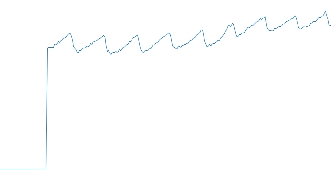
将输出数据转成曲线
假设我做了一个模块如下:m=Module.newdoclassCendend三个问题:除了对m的引用之外,还有什么方法可以访问C和m中的其他内容?我可以在创建匿名模块后为其命名吗(就像我输入“module...”一样)?如何在使用完匿名模块后将其删除,使其定义的常量不再存在? 最佳答案 三个答案:是的,使用ObjectSpace.此代码使c引用你的类(class)C不引用m:c=nilObjectSpace.each_object{|obj|c=objif(Class===objandobj.name=~/::C$/)}当然这取决于
作为我的Rails应用程序的一部分,我编写了一个小导入程序,它从我们的LDAP系统中吸取数据并将其塞入一个用户表中。不幸的是,与LDAP相关的代码在遍历我们的32K用户时泄漏了大量内存,我一直无法弄清楚如何解决这个问题。这个问题似乎在某种程度上与LDAP库有关,因为当我删除对LDAP内容的调用时,内存使用情况会很好地稳定下来。此外,不断增加的对象是Net::BER::BerIdentifiedString和Net::BER::BerIdentifiedArray,它们都是LDAP库的一部分。当我运行导入时,内存使用量最终达到超过1GB的峰值。如果问题存在,我需要找到一些方法来更正我的代
我有一个包含模块的模型。我想在模块中覆盖模型的访问器方法。例如:classBlah这显然行不通。有什么想法可以实现吗? 最佳答案 您的代码看起来是正确的。我们正在毫无困难地使用这个确切的模式。如果我没记错的话,Rails使用#method_missing作为属性setter,因此您的模块将优先,阻止ActiveRecord的setter。如果您正在使用ActiveSupport::Concern(参见thisblogpost),那么您的实例方法需要进入一个特殊的模块:classBlah
我刚刚被困在这个问题上一段时间了。以这个基地为例:moduleTopclassTestendmoduleFooendend稍后,我可以通过这样做在Foo中定义扩展Test的类:moduleTopmoduleFooclassSomeTest但是,如果我尝试通过使用::指定模块来最小化缩进:moduleTop::FooclassFailure这失败了:NameError:uninitializedconstantTop::Foo::Test这是一个错误,还是仅仅是Ruby解析变量名的方式的逻辑结果? 最佳答案 Isthisabug,or
我想获取模块中定义的所有常量的值:moduleLettersA='apple'.freezeB='boy'.freezeendconstants给了我常量的名字:Letters.constants(false)#=>[:A,:B]如何获取它们的值的数组,即["apple","boy"]? 最佳答案 为了做到这一点,请使用mapLetters.constants(false).map&Letters.method(:const_get)这将返回["a","b"]第二种方式:Letters.constants(false).map{|c
我的假设是moduleAmoduleBendend和moduleA::Bend是一样的。我能够从thisblog找到解决方案,thisSOthread和andthisSOthread.为什么以及什么时候应该更喜欢紧凑语法A::B而不是另一个,因为它显然有一个缺点?我有一种直觉,它可能与性能有关,因为在更多命名空间中查找常量需要更多计算。但是我无法通过对普通类进行基准测试来验证这一点。 最佳答案 这两种写作方法经常被混淆。首先要说的是,据我所知,没有可衡量的性能差异。(在下面的书面示例中不断查找)最明显的区别,可能也是最著名的,是你的
我一直致力于让我们的Rails2.3.8应用程序在JRuby下正确运行。一切正常,直到我启用config.threadsafe!以实现JRuby提供的并发性。这导致lib/中的模块和类不再自动加载。使用config.threadsafe!启用:$rubyscript/runner-eproduction'pSim::Sim200Provisioner'/Users/amchale/.rvm/gems/jruby-1.5.1@web-services/gems/activesupport-2.3.8/lib/active_support/dependencies.rb:105:in`co
按照目前的情况,这个问题不适合我们的问答形式。我们希望答案得到事实、引用或专业知识的支持,但这个问题可能会引发辩论、争论、投票或扩展讨论。如果您觉得这个问题可以改进并可能重新打开,visitthehelpcenter指导。关闭10年前。问题1)我想知道rubyonrails是否有功能类似于primefaces的gem。我问的原因是如果您使用primefaces(http://www.primefaces.org/showcase-labs/ui/home.jsf),开发人员无需担心javascript或jquery的东西。据我所知,JSF是一个规范,基于规范的各种可用实现,prim
本教程将在Unity3D中混合Optitrack与数据手套的数据流,在人体运动的基础上,添加双手手指部分的运动。双手手背的角度仍由Optitrack提供,数据手套提供双手手指的角度。 01 客户端软件分别安装MotiveBody与MotionVenus并校准人体与数据手套。MotiveBodyMotionVenus数据手套使用、校准流程参照:https://gitee.com/foheart_1/foheart-h1-data-summary.git02 数据转发打开MotiveBody软件的Streaming,开始向Unity3D广播数据;MotionVenus中设置->选项选择Unit
文章目录1.开发板选择*用到的资源2.串口通信(个人理解)3.代码分析(注释比较详细)1.主函数2.串口1配置3.串口2配置以及中断函数4.注意问题5.源码链接1.开发板选择我用的是STM32F103RCT6的板子,不过代码大概在F103系列的板子上都可以运行,我试过在野火103的霸道板上也可以,主要看一下串口对应的引脚一不一样就行了,不一样的就更改一下。*用到的资源keil5软件这里用到了两个串口资源,采集数据一个,串口通信一个,板子对应引脚如下:串口1,TX:PA9,RX:PA10串口2,TX:PA2,RX:PA32.串口通信(个人理解)我就从串口采集传感器数据这个过程说一下我自己的理解,